Understanding Plant 3D Spools Generation
What Are Spools?
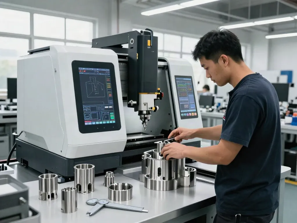
In the context of piping design and construction, spools are pre-assembled sections of piping systems that are fabricated off-site and then transported to the installation location. They are crucial for simplifying installation and reducing on-site assembly time. Spools are typically made up of pipes, fittings, and sometimes even some segments of the pipe support structures, all welded or joined according to specific engineering designs. Efficient spool design can significantly mitigate installation errors and enhance productivity.
The Importance of Efficient Spooling
Efficient spooling plays a pivotal role in the construction and maintenance of large piping systems. By using spools, engineers can minimize assembly time and labor costs associated with on-site installation. Furthermore, pre-assemblies allow for better quality control since skilled workers can focus on fabrication in a controlled environment before transportation to the final location. Enhanced efficiency not only decreases project timelines but also leads to less material waste and reduced costs overall.
Overview of Plant 3D Technology
Autodesk's Plant 3D is a powerful design software that allows engineers and designers to create complex piping systems with a high degree of accuracy. It integrates with other modules that provide functionalities for structural design, equipment modeling, and data management, making it comprehensive for plant design. One of the standout features is its ability to facilitate Plant 3D spools generation, which automates much of the process that previously required extensive manual labor. This feature not only speeds up the design workflow but also ensures accuracy in the generated spools.
Step-by-Step Guide to Plant 3D Spools Generation
Preparation: Requirements and Setup
Before diving into spooling in Plant 3D, ensure you have a well-organized model and the appropriate settings configured within the software. Key requirements include:
- A detailed piping model, complete with all necessary components.
- An established drawing template that includes standard settings for spool drawings.
- Proper access rights to relevant project files and configurations.
- Knowledge of the spooling process and terminology.
Creating and Naming Spools Effectively
Establishing a clear naming convention is integral during spool creation. Proper spool numbering helps in managing and tracking spools throughout the design and implementation phases. It's advisable to adopt a systematic approach for naming, incorporating project identifiers, spool numbers, and possibly even descriptions. Here’s a simple guide for effective naming:
- Use consistent prefixes to denote type or location (e.g., "P1-" for spools related to Pipe Line 1).
- Include numerical sequences for easy identification, ensuring no duplicates.
- Utilize metadata features in Plant 3D to embed length, weight, and material specifications directly into the spool names.
Using the Fabrication Drawing Tools
Once spools are defined and named, the next step is to utilize the fabrication drawing tools in Plant 3D. This involves:
- Selecting the correct piping segments that are part of the spool.
- Defining the spools using the “Generate Spools” command found within the Fabrication environment.
- Reviewing and adjusting the generated spool drawings to ensure they meet design specifications.
This automated process not only saves time but also helps in reducing errors in the drawings. Ensure to periodically verify the created drawings against the original model to maintain accuracy.
Best Practices for Spooling in Plant 3D
Common Challenges and How to Overcome Them
Despite the advantages of using Plant 3D for spooling, users often face common challenges:
- Naming Conflicts: Ensure all spools have unique identifiers to avoid overlaps.
- Integration Issues: Regularly update your software to maintain compatibility with the latest features and fixes.
- Design Accuracy: Utilize Plant 3D’s validation tools to check for design errors before finalizing spools.
Administering a robust checklist for spool creation can significantly diminish these challenges, ensuring a smooth operational flow.
Ensuring Consistency and Accuracy in Drawings
Consistency across drawings is key to avoiding confusion during construction. This involves:
- Adopting standard practices for all drawings, including symbols, annotations, and line types.
- Maintaining a clear, centralized database for all project drawings to ensure teams are working from the latest versions.
- Implementing periodic reviews of spool drawings against set standards and project specifications.
Leveraging Automation for Spool Creation
The automation features in Plant 3D greatly enhance efficiency in spool creation. By setting up rules and templates, users can generate spools quickly and ensure they conform to predefined standards. Automation not only speeds up processes but also provides a consistent output, reducing the potential for human error. Start by exploring the automation features available in the software and create templates tailored to your project's needs.
Advanced Techniques for Professionals
Integrating Other Software Tools
For sophisticated projects, integrating Plant 3D with other software tools can enhance functionality and streamline processes. Consider the following integrations:
- Project Management Software: Using tools like Microsoft Project can help track the progress of spool production and installation.
- BIM Software: Linking Plant 3D with Building Information Modeling tools ensures that designs remain consistent across disciplines.
- Data Management Platforms: Utilizing a central data repository helps in sharing critical information among stakeholders efficiently.
Customizing Spool Generation Settings
To tailor the spool generation process to specific project needs, leverage the customization features in Plant 3D. Adjust spool generation settings based on project requirements, including:
- Spool selection criteria (e.g., size, type, system).
- Naming conventions that reflect project standards.
- Export settings for easy file management and compatibility with other applications.
Taking the time to set these parameters can lead to significant long-term efficiencies.
Performance Metrics for Evaluating Spool Designs
To ensure that spool designs meet project goals, implement performance metrics that evaluate efficiency, cost, and quality. Key metrics include:
- Design accuracy (frequency of changes needed).
- Time taken from design approval to installation.
- Cost overruns associated with fabrication.
Regularly review these metrics to identify areas for improvement and to optimize future spool designs.
FAQs About Plant 3D Spools Generation
What is the best way to start with Plant 3D spools generation?
Begin with understanding the software interface and spooling features, followed by practicing with small projects.
How can I ensure accuracy in my spool drawings?
Regularly verify design specifications, and utilize automation tools for precision in naming and measuring.
What are common issues in spool creation?
Challenges often include naming conflicts and integration with other design elements, so thorough checks and setups are essential.
Can Plant 3D spools be integrated with other CAD tools?
Yes, many users integrate Plant 3D with other software through export functionalities and APIs to enhance project workflows.
How do I optimize the spooling process in Plant 3D?
Utilize automation settings for batch spooling and maintain a consistent naming convention to save time and improve clarity.